


Polar Alignment
Polar Alignment Assitant
When setting up a German Equatorial Mount (GEM) for imaging, a critical aspect of capturing long-exposure images is to ensure a proper polar alignment. A GEM mount has two axis: Right Ascension (RA) axis and Declination (DE) axis. Ideally, the RA axis should be aligned with the celestial sphere polar axis. A mount's job is to track the stars motion around the sky, from the moment they rise at the eastern horizon, all the way up across the median, and westward until they set.
The key is that you need a clear view of some stars, but they don't specifically need to be Polaris. The tool will analyze the star's movement pattern to determine the alignment corrections needed.
However, for best results:
- Choose a star that's relatively high in the sky (around 30-60 degrees altitude)
- Make sure your mount is roughly aligned (within several degrees)
- Ensure your mount is level
- Use a star that isn't too close to the meridian
Hour Angle (HA) and Altitude limits must be turned off when using PAA tool as they can interfere with its operations. Check the Hour Angle and Altitude limits in the Ekos Mount tab
In long exposure imaging, a camera is attached to the telescope where the image sensor captures incoming photons from a particular area in the sky. The incident photons have to strike the same photo-site over and over again if we are to gather clear and crisp image. Of course, actual photons do not behave in this way: optics, atmosphere, seeing quality all scatter and refract photons in one way or another. Furthermore, photons do not arrive uniformly but follow a Poisson distribution. For point-like sources like stars, a point spread function describes how photons are spatially distributed across the pixels. Nevertheless, the overall idea we want to keep the source photons hitting the same pixels. Otherwise, we might end up with an image plagued with various trail artifacts.
Since mounts are not perfect, they cannot perfectly keep track of object as it transits across the sky. This can stem from many factors, one of which is the misalignment of the mount's Right Ascension axis with respect to the celestial pole axis. Polar alignment removes one of the biggest sources of tracking errors in the mount, but other sources of error still play a factor. If properly aligned, some mounts can track an object for a few minutes with only deviation of 1-2 arcsec RMS.
However, unless you have a top of the line mount, then you'd probably want to use an autoguider to keep the same star locked in the same position over time. Despite all of this, if the axis of the mount is not properly aligned with the celestial pole, then even a mechanically-perfect mount would lose tracking with time. Tracking errors are proportional to the magnitude of the misalignment. It is therefore very important for long exposure imaging to get the mount polar aligned to reduce any residual errors as it spans across the sky.
Before starting the process, point the mount as close as possible to the celestial pole. If you are living in the Northern Hemisphere, point it as close as possible to Polaris.

Plate Solve Correction Scheme
The images below show the workflow when the Plate Solve correction technique is used. The image below shows a display after the 3 measurement images are captured and solved. It shows an error of almost 18' in altitude and that the mount's axis needs to be moved up. Similarly it shows an azimuth error of almost 15' and that the axis needs to be moved to the right (as viewed from behind the telescope).
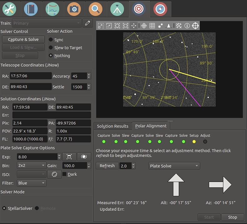
If your error is low enough (e.g. less than an arc-minute) then you don't need to make any adjustments. Simply press stop and you're done.
If you will be making corrections to your mount's axis, you should select the adjustment approach (we're using Plate Solve in this example), and how often the system should recapture images to re-measure the polar alignment error. The refresh interval should be frequent, but it doesn't make sense to make it faster that your CPU can capture and plate-solve the images. We're using 2s in this example. Then press the button to begin the correction process.
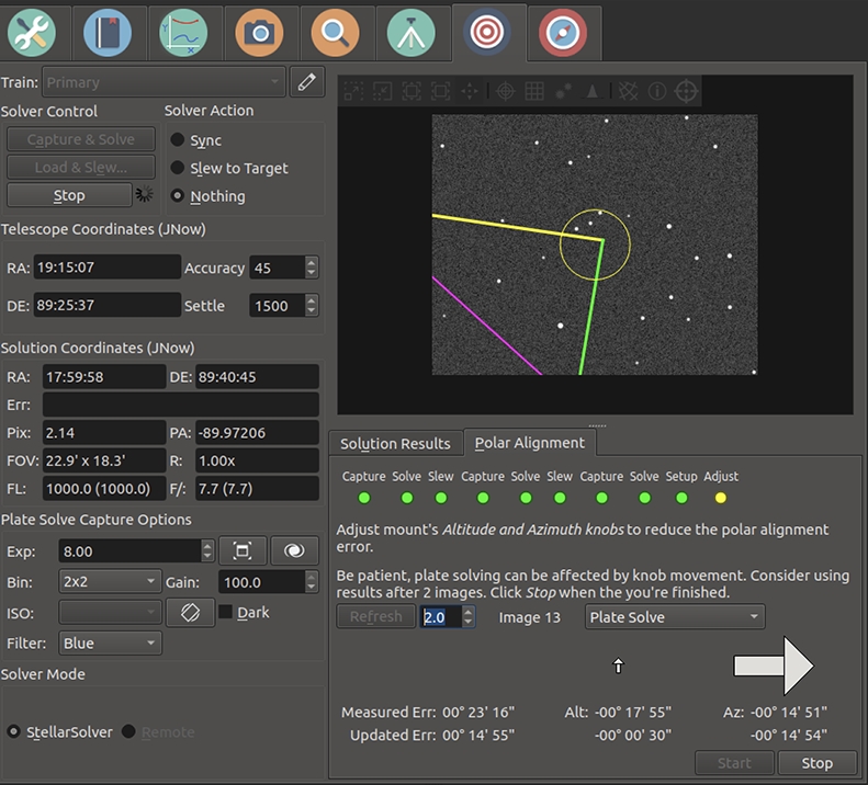
The system will capture images, and re-estimate the polar alignment error after each image. You can try to reduce the error by adjusting the Altitude and Azimuth correction knobs on your mount. The image below shows the screen after the altitude error has been almost zeroed. See the difference between the Measured Error row, which shows the originally measured error after the original 3 captures, and the Updated Error row which shows the current error estimate.
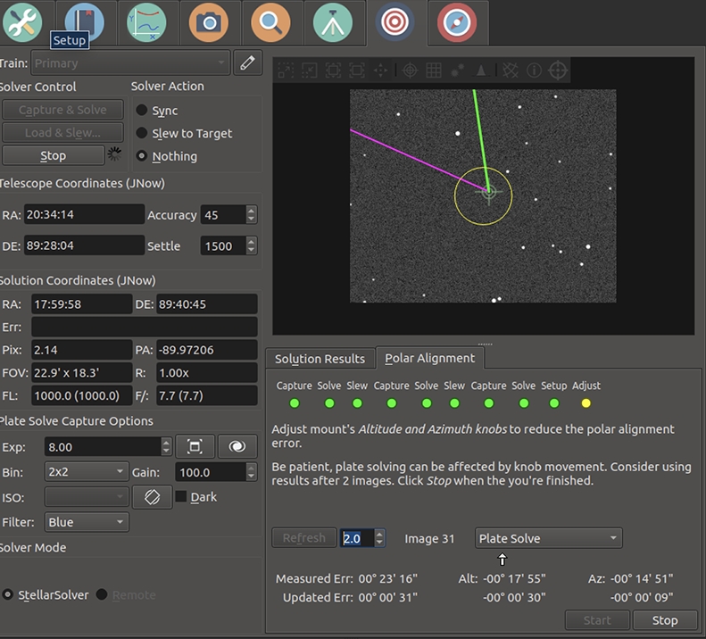
Below the user has also adjusted Azimuth to reduce the error further. Now the error is very low and the process is done. The user should press the stop button.
Move Star Correction Scheme
We also have an alternative schemes for correcting polar alignment. Two variations are Move Star & Calc Error and Move Star. When you select this scheme, the system place a yellow/green/violet triangle on the screen. The triangle can be moved by clicking near a star, and the yellow/violet corner is moved to that star. In this scheme the user corrects polar alignment by first adjusting the mount's azimuth knob so that the selected star moves along the yellow side of the triangle. Once the star is near the next vertex, the azimuth knob should be adjusted so that the star moves along the green side of the triangle. Once the star is moved to the green/violet vertex, the mount is polar aligned, and the user can click stop.The difference between Move Star & Calc Error and Move Star is that in the former, the system attempts to track the star the user has selected, and places a circle around that star. In that scheme it also attempts to update the Updated Err row. If the star tracking isn't reliable, simply ignore it or use the Move Star scheme and move the star by-eye until it's close to the final target. An example of using this technique is shown in this video: https://www.youtube.com/watch?v=iOp7hrxw0oU