Polar Alignment

Polar Alignment Assitant

When setting up a German Equatorial Mount (GEM) for imaging, a critical aspect of capturing long-exposure images is to ensure a proper polar alignment. A GEM mount has two axis: Right Ascension (RA) axis and Declination (DE) axis. Ideally, the RA axis should be aligned with the celestial sphere polar axis. A mount's job is to track the stars motion around the sky, from the moment they rise at the eastern horizon, all the way up across the median, and westward until they set.

The key is that you need a clear view of some stars, but they don't specifically need to be Polaris. The tool will analyze the star's movement pattern to determine the alignment corrections needed.
However, for best results:

  • Choose a star that's relatively high in the sky (around 30-60 degrees altitude)
  • Make sure your mount is roughly aligned (within several degrees)
  • Ensure your mount is level
  • Use a star that isn't too close to the meridian

Hour Angle (HA) and Altitude limits must be turned off when using PAA tool as they can interfere with its operations. Check the Hour Angle and Altitude limits in the Ekos Mount tab

In long exposure imaging, a camera is attached to the telescope where the image sensor captures incoming photons from a particular area in the sky. The incident photons have to strike the same photo-site over and over again if we are to gather clear and crisp image. Of course, actual photons do not behave in this way: optics, atmosphere, seeing quality all scatter and refract photons in one way or another. Furthermore, photons do not arrive uniformly but follow a Poisson distribution. For point-like sources like stars, a point spread function describes how photons are spatially distributed across the pixels. Nevertheless, the overall idea we want to keep the source photons hitting the same pixels. Otherwise, we might end up with an image plagued with various trail artifacts.


Since mounts are not perfect, they cannot perfectly keep track of object as it transits across the sky. This can stem from many factors, one of which is the misalignment of the mount's Right Ascension axis with respect to the celestial pole axis. Polar alignment removes one of the biggest sources of tracking errors in the mount, but other sources of error still play a factor. If properly aligned, some mounts can track an object for a few minutes with only deviation of 1-2 arcsec RMS.

However, unless you have a top of the line mount, then you'd probably want to use an autoguider to keep the same star locked in the same position over time. Despite all of this, if the axis of the mount is not properly aligned with the celestial pole, then even a mechanically-perfect mount would lose tracking with time. Tracking errors are proportional to the magnitude of the misalignment. It is therefore very important for long exposure imaging to get the mount polar aligned to reduce any residual errors as it spans across the sky.

Before starting the process, point the mount as close as possible to the celestial pole. If you are living in the Northern Hemisphere, point it as close as possible to Polaris.

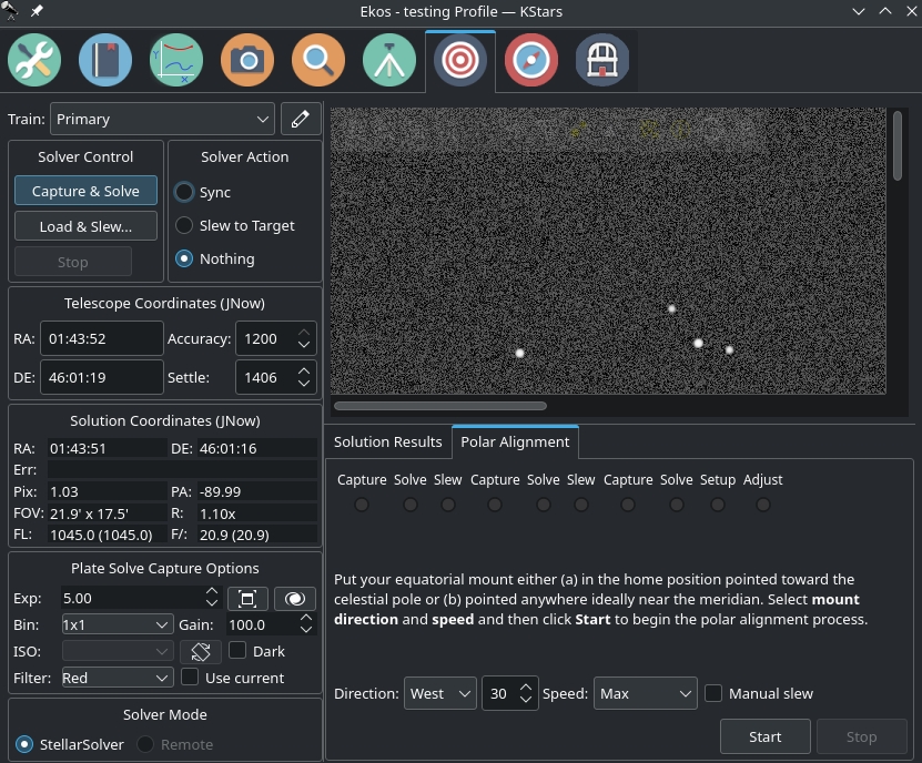
The tool works by capturing and solving three images. After capturing each, the mount rotates by the fixed amount you entered and another image is captured and solved. If you choose manual, you must slew the mount roughly at the chosen angle.

polar align start


Plate Solve Correction Scheme

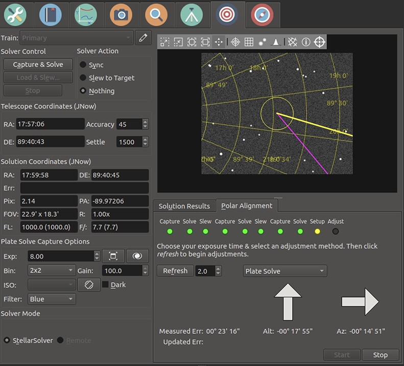
The images below show the workflow when the Plate Solve correction technique is used. The image below shows a display after the 3 measurement images are captured and solved. It shows an error of almost 18' in altitude and that the mount's axis needs to be moved up. Similarly it shows an azimuth error of almost 15' and that the axis needs to be moved to the right (as viewed from behind the telescope).

start refresh


If your error is low enough (e.g. less than an arc-minute) then you don't need to make any adjustments. Simply press stop and you're done.

If you will be making corrections to your mount's axis, you should select the adjustment approach (we're using Plate Solve in this example), and how often the system should recapture images to re-measure the polar alignment error. The refresh interval should be frequent, but it doesn't make sense to make it faster that your CPU can capture and plate-solve the images. We're using 2s in this example. Then press the Refresh button to begin the correction process.

The system will capture images, and re-estimate the polar alignment error after each image. You can try to reduce the error by adjusting the Altitude and Azimuth correction knobs on your mount. The image below shows the screen after the altitude error has been almost zeroed. See the difference between the Measured Error row, which shows the originally measured error after the original 3 captures, and the Updated Error row which shows the current error estimate.

image 13

Below the user has also adjusted Azimuth to reduce the error further. Now the error is very low and the process is done. The user should press the stop button.

image 31

Move Star Correction Scheme

We also have an alternative schemes for correcting polar alignment. Two variations are Move Star & Calc Error and Move Star. When you select this scheme, the system place a yellow/green/violet triangle on the screen. The triangle can be moved by clicking near a star, and the yellow/violet corner is moved to that star. In this scheme the user corrects polar alignment by first adjusting the mount's azimuth knob so that the selected star moves along the yellow side of the triangle. Once the star is near the next vertex, the azimuth knob should be adjusted so that the star moves along the green side of the triangle. Once the star is moved to the green/violet vertex, the mount is polar aligned, and the user can click stop.The difference between Move Star & Calc Error and Move Star is that in the former, the system attempts to track the star the user has selected, and places a circle around that star. In that scheme it also attempts to update the Updated Err row. If the star tracking isn't reliable, simply ignore it or use the Move Star scheme and move the star by-eye until it's close to the final target. An example of using this technique is shown in this video: https://www.youtube.com/watch?v=iOp7hrxw0oU


Introduction

analyzeThe Analyze Module records and displays what happened in an imaging session. That is, it does not control any if your imaging, but rather reviews what occurred. Sessions are stored in an analyze folder, a sister folder to the main logging folder. The .analyze files written there can be loaded into the Analyze tab to be viewed. Analyze also can display data from the current imaging session.The Analyze Module records and displays what happened in an imaging session. That is, it does not control any if your imaging, but rather reviews what occurred. Sessions are stored in an analyze folder, a sister folder to the main logging folder. The .analyze files written there can be loaded into the Analyze tab to be viewed. Analyze also can display data from the current imaging session.


There are two main graphs, Timeline and Stats. They are coordinated—they always display the same time interval from the Ekos session, though the x-axis of the Timeline shows seconds elapsed from the start of the log, and Stats shows clock time. The x-axis can be zoomed in and out with the +/- button, mouse wheel, as well as with standard keyboard shortcuts (eg. zoom-in == Ctrl +) The x-axis can be panned with the scroll bar as well as with the left and right arrow keys. You can view your current imaging session, or review old sessions by loading .analyze files using the Input dropdown. Checking Full Width displays all the data, and Latest displays the most recent data (you can control the width by zooming). 

Timeline

Timeline shows the major Ekos processes, and when they were active. For instance, the Capture line shows when images were taken (green sections) and when imaging was aborted (red sections). Clicking on a green section gives information about that image, and double clicking on one brings up the image taken then in a fitsviewer, if it is available.Timeline shows the major Ekos processes, and when they were active. For instance, the Capture line shows when images were taken (green sections) and when imaging was aborted (red sections). Clicking on a green section gives information about that image, and double clicking on one brings up the image taken then in a fitsviewer, if it is available.


If you have moved your captured images, you can set alternate directory in the input menu to a directory which is the base of part of the original file path.


Clicking on a Focus segment shows focus session information and displays up the position vs HFR measurements from that session. Clicking on a Guider segment shows a drift plot from that session, (if it's guiding) and the session's RMS statistics. Other timelines show status information when clicked. 

Statistics

A variety of statistics can be displayed on the Stats graph. There are too many for all to be shown in a readable way, so select among them with the checkboxes. A reasonable way to start might be to use rms, snr (using the internal guider with SEP Multistar), and hfr (if you have auto-compute HFR in the FITS options). Experiment with others. The axis shown (0-5) is appropriate only for ra/dec error, drift, rms, pulses, and hfr. These may be y-axis scaled (awkwardly) using the mouse wheel, but the other graphs cannot be scaled. To reset y-axis zooming, right-click on the Stats plot. Clicking on the graph fills in the values of the displayed statistics. This graph is zoomed and panned horizontally in coordination with the timeline.


Introduction

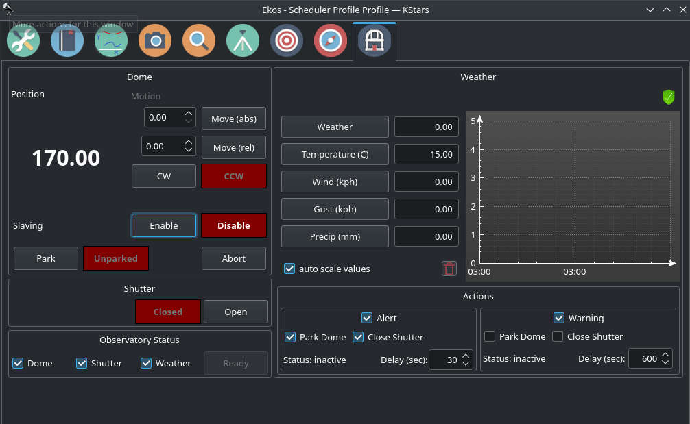
The observatory module is used to manage the dome and weather-triggered shutdown procedure. It has weather data directly displayed in the module. Along with the configurable thresholds for Warning and Alert states, you can rest easily knowing that KStars can take the appropriate actions to protect your observatory from adverse weather conditions. The observatory module also includes a dedicated weather widget with love plotting for each parameter.

observatory

Dome

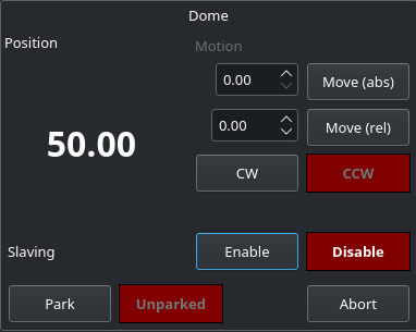
  • Position: Controls the position of the Dome.observatory dome
    • Motion: You can move the Dome in four ways.
      • Absolute: Select the absolute position you want the Dome to move and then click on Move (abs). This will move the Dome to the absolute position you set.
      • Relative: Select the amount of degrees (either positive or negative) you want the Dome to move from the current position and then click on Move (rel). This will move the Dome to the relative position you set.
      • Clockwise (CW): Rotates the Dome Clockwise forever until you click on Abort.
      • Counter Clockwise (CCW): Rotates the Dome Clockwise forever until you click on Abort.
  • Slaving: If enabled, Dome motion will follow telescope motion.
  • Park/Unpark: Park or Unpark the Dome. For advanced control, please use the INDI Control Panel.
  • Abort: Aborts the Dome motion.

Shutterobservatory shutter

  • Open/Close: You can open or close your shutter through the observatory module.

Observatory Status

  • Dome: If selected, the dome needs to be unparked for the observatory status being "READY".observatory status
  • Shutter: If selected, the shutter needs to be open for the observatory status being "READY".
  • Weather: If selected, the weather needs to be OK for the observatory status being "READY".
  • Ready: Observatory status. Select the observatory elements that are relevant for the status:
    • Dome: unparked → ready
    • Shutter: open → ready
    • Weather: OK → ready

Weatherobservatory weather widget

Current data of the weather sensors. Click on the sensor name to display its data over time.

  • auto scale values: Scale the value axis to the current value range.
  • trash canClear sensor data history.
  • Graph: You can see the values of both axes if you hover over the graph. You can zoom in or out using the scroll wheel.

Actions

  • Alert: Check this checkbox in order to get an Alert whenever any weather value goes under or above the range set in your weather driver INDI Control Panel.
    • Park Dome: Parks the dome whenever you get an alert.observatory actions
    • Close Shutter: Closes the shutter whenever you get an alert.
    • Status: Shows the status of the alert.
    • Delay (sec): Delays the alert after n amount of seconds.
  • Warning: Check this checkbox in order to get an Warning whenever any weather value is close to going under or above the range set in your weather driver INDI Control Panel.
    • Park Dome: Parks the dome whenever you get a warning.
    • Close Shutter: Closes the shutter whenever you get a warning.
    • Status: Shows the status of the warning.
    • Delay (sec): Delays the warning after n amount of seconds.

ekos scheduler

Introduction

Ekos Scheduler is an indispensable arsenal in building your robotic observatory. A Robotic observatory is an observatory composed of several subsystems that are orchestrated together to achieve a set of scientific objectives without direct human intervention. 

It’s recommended to use Ekos Scheduler after you are familiar with using all the Ekos modules manually first. Fine-tune the settings for each module to suit your particular equipment setup.

Settings

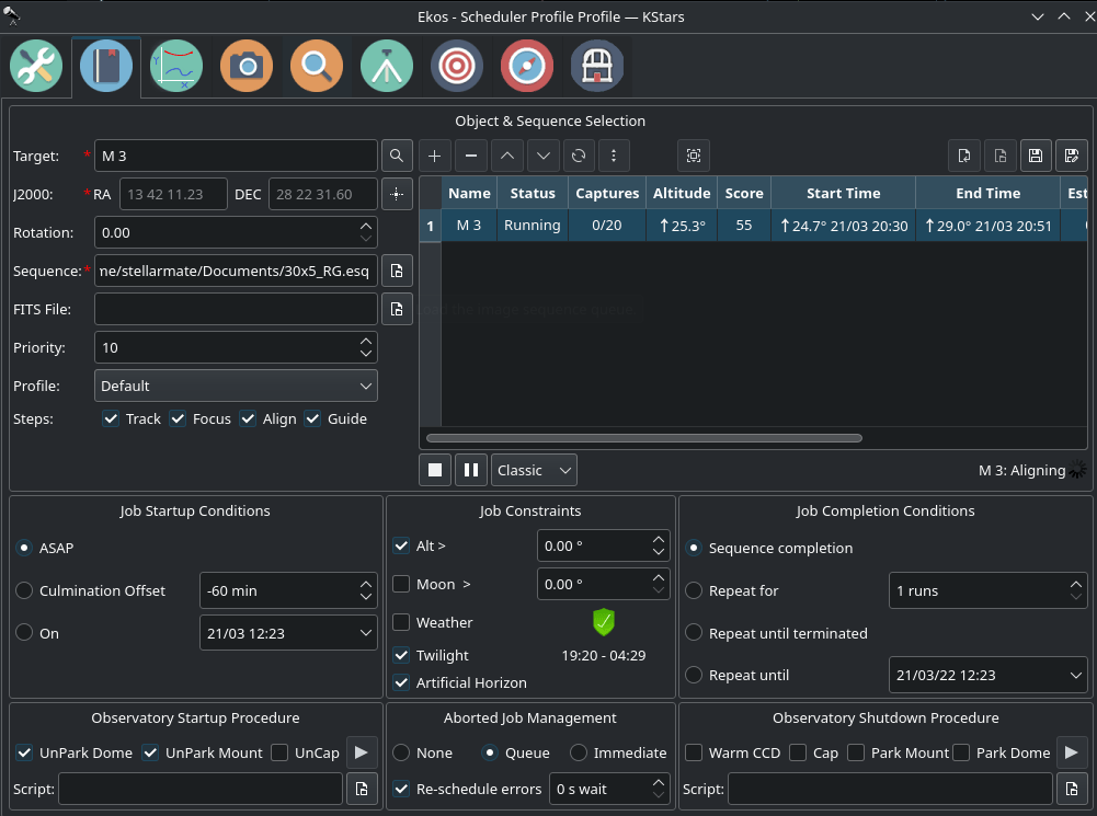
Ekos Scheduler provides a simple interface to aid the user in setting the conditions and constraints required for an observation job. Each observation job is composed of the following:

  • Target name and coordinates: Select the target from the Find Dialog or Add it from the Observation Planner. You can also enter a custom name.
  • Optional FITS file: If a FITS file is specified, the astrometry solver shall solve the file and use the central RA/DEC as the target coordinates.
  • Sequence File: The sequence file is constructed in the Ekos Capture Module. It contains the number of images to capture, filters, temperature settings, prefixes, download directory..etc.
  • Priority: Set job priority in the range of 1 to 20 where 1 designates the highest priority and 20 the lowest priority. Priority is applied in calculating the weight used to select the next target to image. (Only enabled in Classic algorithm)
  • Profile: Select which equipment profile to utilize when starting Ekos. If Ekos & INDI are already started and online, this selection is ignored.
  • Steps: Each job goes through a sequence of discrete steps. Each step or stage can be toggled on or off as desired:
      1. Track: Mount is commanded to slew to target.
      2. Focus: Camera autofocus (if applicable) is started.
      3. Align: Plate-solving is performed to ensure the correct location, framing and orientation of the target is met. If a FITS file is specified in General Settings, then this file is first plate-solved and then mount is commanded to to slew to target solution coordinates. This is followed by another plate-solving process to ensure we are within tolerance at the target solution coordinates. If the position angle of the FITS image is different from the current camera orientation, the camera orientation can be automatically adjusted if a mechanized rotator is detected. Otherwise, a manual camera rotation is required until the image position angle is satisfied.
      4. Guide: Using a guide camera, the mount tracking is locked to a guide star to enable long-exposure astrophotography
  • Startup Conditions: Conditions that must be met before the observation job is started. Currently, the user may select to start as soon as possible Now, or when the target is near or past culmination, or at a specific time.
  • Constraints: Constraints are conditions that must be met at all times during the observation job execution process. These include minimum target altitude, minimum moon separation, twilight observeration, and weather monitoring.
  • Completion Conditions: Conditions that trigger completion of the observation job. The default selection is to simply mark the observation job as complete once the sequence process is complete. Additional conditions enable the user to repeat the sequence process indefinitely or up until a specific time.

You must select the Target and Sequence before you can add a job to the Scheduler. When the scheduler starts, it evaluates all jobs in accordance to the conditions and constraints specified and attempts to select the best job to execute. Selection of the job depends on a simple heuristic algorithm that scores each job given the conditions and constraints, each of which is weighted accordingly. If two targets have identical conditions and constraints, usually the higher priority target followed by higher altitude target is selected for execution. If no candidates are available at the current time, the scheduler goes into sleep mode and wakes up when the next job is ready for execution.

toggle mosaic

The description above only tackles the Data Acquisition stage of the observatory workflow. The overall procedure typically utilized in an observatory can be summarized in three primary stages:

  1. Startup
  2. Data Acquisition (including preprocessing and storage)
  3. Shutdown

Startup Procedure

Startup procedure is unique to each observatory but may include:

  • Turning on power to equipment
  • Running safety/sanity checks
  • Checking weather conditions
  • Turning off light
  • Fan/Light control
  • Unparkig dome
  • Unparking mount
  • ..etc

Ekos Scheduler only initiates the startup procedure once the startup time for the first observation job is close (default lead time is 5 minutes before startup time). Once the startup procedure is completed successfully, the scheduler picks the observation job target and starts the sequence process. If a startup script is specified, it shall be executed first.

Data Aquisition

Depending the on the user selection, the typical workflow proceeds as following:

  • Slew mount to target. If a FITS file was specified, it first solves the files and slew to the file coordinates.
  • Auto-focus target. The autofocus process automatically selects the best star in the frame and runs the autofocus algorithm against it.
  • Perform plate solving, sync mount, and slew to target coordinates.
  • Perform post-alignment focusing since the frame might have moved during the plate solving process.
  • Perform calibration and start auto-guiding: The calibration process automatically selects the best guide star, performs calibration, and starts the autoguide process.
  • Load the sequence file in the Capture module and start the imaging process.

Shutdown

Once the observation job is completed successfully, the scheduler selects the next target. If the next target scheduled time is not due yet, the mount is parked until the target is ready. Furthermore, if the next scheduled target is not due for a user-configurable time limit, the scheduler performs a preemptive shutdown to preserve resources and performs the startup procedure again when the target is due.

If an unrecoverable error occurs, the observatory initiates shutdown procedure. If there is a shutdown script, it will be executed last.

The following video demonstrates an earilar version of the scheduler, but the basic principles still apply today:


The Greedy Scheduler

Greedy Scheduler will allow you to choose a new scheme for scheduling jobs. (In the nightly release) there should now be a scheduling algorithm choice. If you set it to "Classic" (the default), nothing has changed. If you set it to "Greedy" you will see the changes described below.  Note: these changes concern scheduling--deciding which jobs run and when. They do not affect the job management aspects of the scheduler which remain unchanged.

In both the Classic and Greedy schedulers, jobs are listed as "earlier on the job list means higher priority". With the Classic scheduler, priority** is of the highest importance. It will not schedule a lower priority job until the higher priority job is done, even if that job takes several nights, and even if the higher-priority job cannot run at the current time, e.g. due to altitude/terrain/etc.  In contrast to this, the Greedy scheduler attempts to keep Ekos busy as much as possible. Although it gives priority to earlier-listed-jobs, it will run later-listed ones if the earlier one can't run. Of course, the lower priority job will get preempted when the high-priority job can finally start to run.

**In this discussion, "lower priority" means "further down on the job list". and similarly, a higher priority is higher/earlier on the job list. We will be phasing out the priority number that can be assigned to jobs on the Classic scheduler.

If the scheduler is started with only one job, there is no difference between Classic and Greedy scheduling. However, if you have more than one job, depending on your setup, there is a good chance that the Greedy scheduler will schedule more imaging time than Classic.

Here's a recommended way to try this out. Let's assume you have a main target for which you want to collect as many images as possible. Set that target up as first on the scheduler list, have it start ASAP and set its completion condition as "Repeat Until Terminated". It should be scheduled to image whenever possible (even across multiple nights) until you turn off the scheduler or Ekos. Add several other targets as well, ones that you might also be interested in, and that can be imaged in other parts of the night. Make sure those are listed below the primary target on the jobs list. Set those the same way (ASAP/RepeatUntilTerminated). They will be scheduled to run whenever the primary target can't be imaged.  Of course, make sure the twilight restriction is set for all your targets. Altitude and terrain restrictions are important as well--if Ekos doesn't know that there's a tree or house blocking your target, it can't be smart about scheduling it.

Since jobs will be preempted/restarted more often with Greedy than with Classic, the "Remember Job Progress" option is now more important. Can find this setting in the KStars Setting Menu --> Ekos --> Scheduler --> "Remember job progress".  This option only works if you are storing images on the same machine where the scheduler is running. Should enable "Remember Job Progress" with this scheduler to get the most benefit, assuming your capture sequences use multiple/different filters. If your capture sequences are just used with one type of filter/or OSC then it probably doesn't matter. (RememberJobProgress has also be updated a bit, and should now do a better job of picking up where the last attempt finished.)

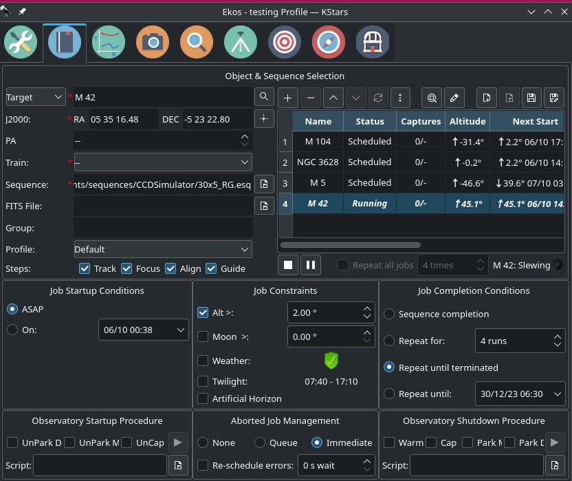
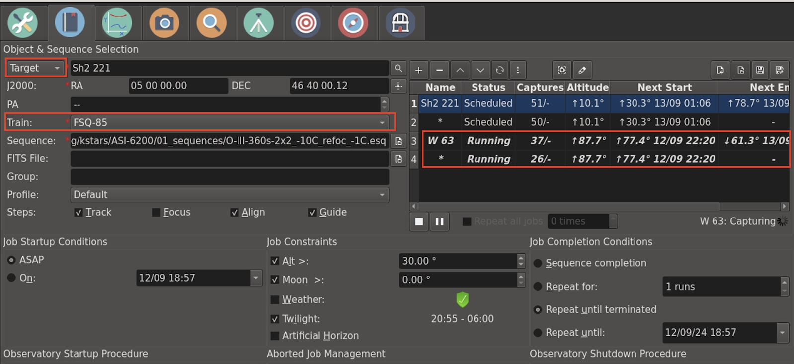
Here is a screenshot of the scheduler running with this new scheme. Note that there are 4 jobs, and they are listed in order of precedence. See the next start times for each of the jobs on the scheduler table, and the highlighted (4th) job is the one currently running. A schedule for the next 48 hours is also printed in the log window at the bottom.

greedyScheduler2

The scheduler is (minimally) integrated with Analyze. Here's a screenshot of the Analyze timeline for the 3 days. (Note some timelines didn't display well because of screen resolution.)  The top line is the new scheduler timeline in Analyze. The different colors correspond to different jobs that were run, each one keeping its same color on different stars (yes, red is an unfortunate choice of colors and I've already submitted code that changes the color scheme for that line). Different jobs can be seen ran as expected each night.

Multi-Target Scheduler

Wolfgang Reissenberger continued the development of multi-camera acquisition and now scheduling with many exciting updates!

multi camera

Multi-Camera Scheduling

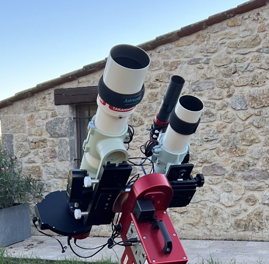
With this new release it is possible to create and run schedules for two or more optical trains in parallel within the same KStars instance. All mount related events like slewing, dithering, alignment and meridian flip are synchronized, i.e. capturing on all optical trains takes these events into account.

telescope


Lead and follower jobs

If you want to run capturing on multiple optical trains in parallel, you need to decide, which of the optical trains is the lead job, which defines the target and the scheduling criteria. All other optical trains will be follower jobs, for which only the capture sequence to be used is relevant.

Job Synchronization

Ekos ensures that no mount motion happens while one of the optical trains is capturing to avoid star trails.

In the case of dithering, the capture module decides what to do as soon as dithering is requested, depending on the setup of the lead job. If the remaining capture time of a follower train is more than 50% of the lead job exposure time, capturing of the follower train is stopped and restarted after dithering. If the remaining capture time is less than 50%, the Capture module waits for the follower to finish its capture.

For the meridian flip and re-alignment: both are controlled by the lead job. All running follower-capturing sequences are stopped and restarted after the successful completion of the respective action.

Recommendations

  • The lead job should have the longest exposure times, especially if dithering is used.
  • If you use re-focusing, consider not suspending guiding during focusing, since the other optical train might capture in parallel.
  • Configure the same optical train in the Align module that you use in the lead job. This is important if you use the re-alignment check option of the scheduler.

Do not use the Force re-alignment before re-starting jobs, since each new iteration of the lead job stops capturing of the follower trains. Consider using Verify captured image position every n frames instead, since this option triggers re-alignment only if it is necessary.


Greedy3dayB

Weather Monitoring

Another critical feature of any remotely operated robotic observatory is weather monitoring. For weather updates, Ekos relies on the selected INDI weather driver to continuously monitor the weather conditions. For simplicity sake, the weather conditions can be summed in three states:

  1. Ok: Weather conditions are clear and optimal for imaging.
  2. Warning: Weather conditions are not clear, seeing is subpar, or partially obstructed and not suitable for imaging. Any further imaging process is suspended until weather improves. Warning weather status does not pose any danger to the observatory equipment so the observatory is kept operational. The exact behavior to take under Warninig status can be configured.
  3. Alert: Weather conditions are detrimental to the observatory safety and shutdown must be initiated as soon as possible.

Aborted Job Management

Define what should happen when a job steps into an error or aborts:

  • Don't re-schedule (None): Don't restart the job in case of an error or an abort.
  • Re-schedule after all terminated (Queue): If a job gets aborted, the scheduler will only re-schedule it if when all jobs are finished or aborted. If this is the case, the scheduler re-schedules all aborted jobs and sleeps for the given delay.
  • Re-schedule immediately (Immediate): As soon as a job gets aborted, the scheduler will re-schedule it and waits the given delay.

If the option for re-scheduling errors is selected, errors are handled like aborts. Otherwise, jobs that step into an error are never re-scheduled.

Startup & Shutdown Scripts

Due to the uniqueness of each observatory, Ekos enables the user to select startup and shutdown scripts. The scripts takes care of any necessary procedures that must take place on startup and shutdown stages. On startup, Ekos executes the startup scripts and only proceeds to the remainder of the startup procedure (unpark dome/unpark mount) if the script completes successfully. Conversely, the shutdown procedure begins with parking the mount & dome before executing the shutdown script as the final procedure.

Startup and shutdown scripts can be written any language that can be executed on the local machine. It must return 0 to report success, any other exist value is considered an error indicator. The script's standard output is also directed to Ekos logger window. The following is as sample demo startup script in Python:

#!/usr/bin/env python
# -*- coding: utf-8 -*-

import os
import time
import sys

print "Turning on observatory equipment..."
sys.stdout.flush()

time.sleep(5)

print "Checking safety switches..."
sys.stdout.flush()

time.sleep(5)

print "All systems are GO"
sys.stdout.flush()

exit(0)

The startup and shutdown scripts must be executable in order for Ekos to invoke them (e.g. use chmod +x startup_script.py to mark the script as executable). Ekos Scheduler enables truly simple robotic operation without the need of any human intervention in any step of the process. Without human presence, it becomes increasingly critical to gracefully recover from failures in any stage of the observation run. Using KDE notifications, the user can configure audible alarms and email notifications for the various events in the scheduler.

Verifying Target Location

Due to a variety of factors, the captured target image might get shifted during the imaging process. Such factors might include:

  • Mount tracking issues.
  • Guiding issues.
  • External factors such as wind or vibrations.

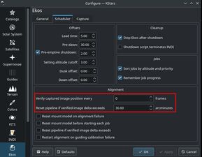
To ensure the target stays centered, configure the scheduler to recheck the image position every few frames. If the captured image position has veered off the original target more than a configure threshold, then the scheduler would immediately abort the imaging and guiding processes, and perform a re-alignment to bring the mount back to the original target. Once this is successfully completed, it would resume the guiding and capturing workflows. You can configure these settings in Settings -> Configure KStars -> Ekos

recheck image

Manual Target Selection

When selecting a target usign the Ekos Find Tool, the objects equatorial coordinates (J2000) are automatically filled in the RA/DE fields. You can also define your own custom target. Simply type in your target name in the target field and then manually enter the desired J2000 coordinates in the respective fields.

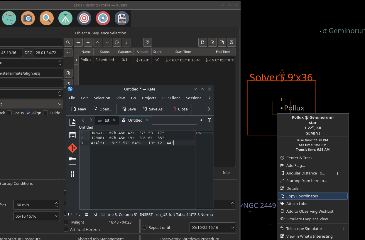
KStars provides a conventient method to Copy Coordinates. Simply right-click on the desired object or point in the sky where you want to image, and click copy coordinates. You can paste the coordinates in any text editor and then copy back the J2000 coordinates in the scheduler RA and DE fields as shown below.

copy coordinates

Mosaic Planner

mosaic planner

Hubble-like super wide field images of galaxies and nebulae are truly awe inspiring, and while it takes great skills to obtain such images and process them; many notable names in the field of astrophotography employ gear that is not vastly different from yours or mine. I emphasize vastly because some do indeed have impressive equipment and dedicated observatories worth tens of the thousands of dollars. Nevertheless, many amateurs can obtain stellar wide-field images by combining smaller images into a single grand mosaic.

We are often limited by our camera+telescope Field of View (FOV). By increasing FOV by means of a focal reducer or a shorter tube, we gain a larger sky coverage at the expense of spatial resolution. At the same time, many attractive wide-field targets span multiple FOVs across the sky. Without any changes to your astrophotography gear, it is possible to create a super mosaic image stitched together from several smaller images. There are two major steps to accomplish a super mosaic image:

  1. Capture multiple images spanning the target with some overlap between images. The overlap is necessary to enable the processing software from aligning and joining the sub-images.
  2. Process the images and stitch them into a super mosaic image.

The 2nd step is handled by image processing applications such as PixInsight, among others, and will not be the topic of discussion here. The first step can be accomplished in Ekos Scheduler where it creates a mosaic suitable for your equipment and in accordance to the desired field of view. Not only Ekos creates the mosaic panels for your target, but it also constructs the corresponding observatory jobs required to capture all the images. This greatly facilitates the logistics of capturing many images with different filters and calibration frames across a wide area of the sky.

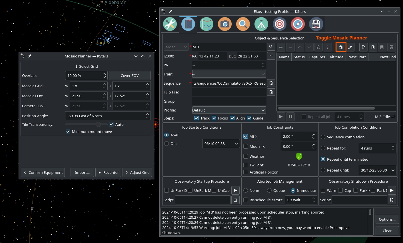
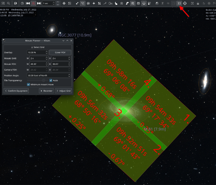
The Mosaic Planner in the Ekos Scheduler will create multiple Scheduler jobs based on a central target. To toggle the planner, click on the Mosaic Planner button in Ekos Scheduler or KStars INDI toolbar as illustrated in the screenshot. The planner draws the Mosaic Panel directly unto the sky map. It is recommended to enable HiPS overlay for the best experience. The planner is composed of four stages:

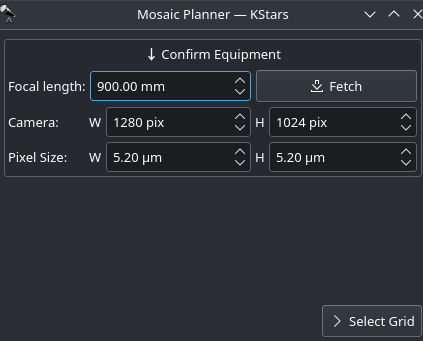
  1. Confirm Equipment: Ekos attempts to load equipment settings from INDI. If unsuccessful, you need to enter your equipment settings including your telescope focal length in addition to camera's width, height, and pixel dimensions. The settings are saved for future sessions.

confirm grip

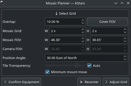
  1. Select Grid: Select the mosaic panel dimension and overlap percentage. The Mosaic Panel is updated accordingly on the sky map. Adjust the Position Angle to match the desired mosaic orientation in the sky. If the Position Angle is different from your camera's usual orientation, you may need to rotate the camera either manually or via a mechanized rotator when the scheduler jobs are executed. Tile transparency is automatically calculated by default but may be turned off and adjusted manually. To compute the mosaic field from the number of tiles, click the Cover FOV button. The mosaic panel can be centered in the sky map by clicking on the Recenter button.

select grid

A large overlap will make frame stitching easier during post-processing, but it requires more panes to cover the desired extent. However, if you already know the minimal amount of sub-frames your rejection algorithm will use during post-processing, you may want to increase the overlap to attain that amount on the areas covered by multiple panes. For instance, a 4x4 mosaic grid with 75% overlap has 16 sub-frames covering the central intersection, which is enough for Winsorized Sigma rejection. Although the resulting stack does not have the same height on all parts of the final frame, this method gives you control on signal-to-noise ratio and allows you to provide context to your target while exposing a relatively low number of captures.

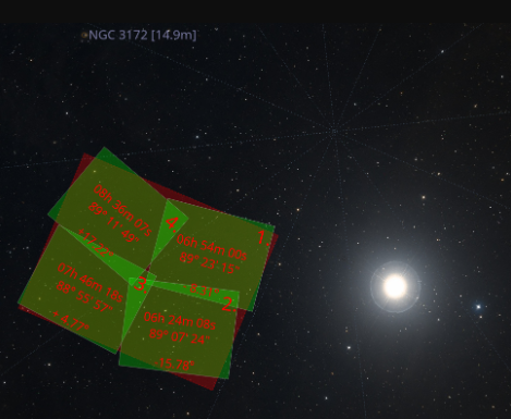
The large number drawn in the corner of each grid pane represents the order in which panes will be captured. The default S-shaped choice (west-east then alternating high-low/low-high moves), ensures minimal movement of the mount during observation. Uncheck Minimum mount move to revert to west-east/high-low movement only. The coordinates of each pane are rendered in their center as degrees, minutes and seconds. Finally, the angle each pane rotates from the center of the mosaic is displayed at the bottom. If your field of view is large, or if your mosaic is located close to a celestial pole, you may observe that rendered panes start rotating visibly due their horizontal position or high declination. Use the overlap to ensure panes cover the desired frame extents properly.

 mosaic grid
 
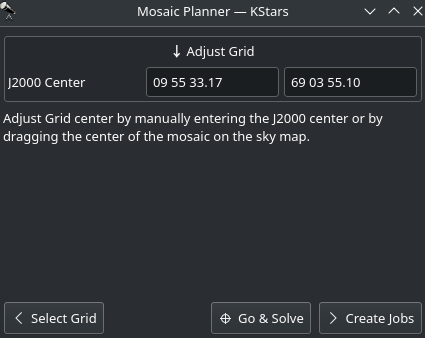
  1. Adjust Grid: Adjust Grid center by manually entering the J2000 center or by dragging the center of the mosaic on the sky map.

adjust grid

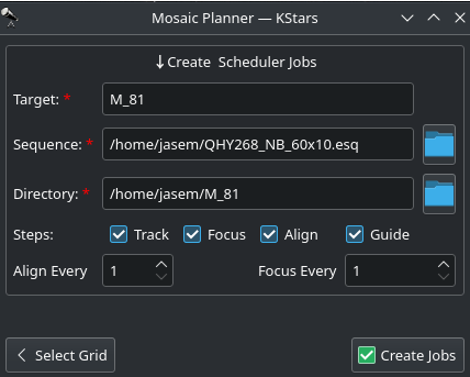
  1. Create Jobs: The final step is to select the sequence file and directory to store the images. Target field is automatically filled but may be changed as desired. Select the steps each scheduler job should execute in sequence (Track -> Focus -> Align -> Guide -> Capture), and adjust the frequency of automatic alignment and focus routines that must be executed during the mosaic operation. For example, if Align Every is set to 2 Scheduler Jobs, then the first job will run the astrometry alignment, while the second job will skip it. When the third job is executed, alignment is performed again and so forth

create scheduler jobs

Click Create Jobs to generate mosaic scheduler jobs and add them to the schedule queue.


{extra_toc}

Introduction

ekos astrometry

Ekos Alignment Module enables highly accurate GOTOs to within sub-arcseconds accuracy and can measure and correct polar alignment errors. This is possible thanks to the StellarSolver library. Ekos begins by capturing an image of a starfield, feeding that image to the solver, and getting the central coordinates (RA, DEC) of the image. The solver essentially performs a pattern recognition against a catalog of millions of stars. Once the coordinates are determined, the true pointing of the telescope is known.

Often, there is a discrepancy between where the telescope thinks it is looking at and where it is truly pointing. The magnitude of this discrepancy can range from a few arcminutes to a couple of degrees. Ekos can then correct the discrepancy by either syncing to the new coordinates, or by slewing the mount to the desired target originally requested.

Furthermore, Ekos provides the Polar Alignment Assitant Tool: An easy to use tool for measuring and correcting polar errors. It takes three images any where in the sky (prefreably close to the celestial poles but not required) and then calculates the offset between the mount axis and polar axis.

At a minimum, you need a camera and a mount that supports Slew & Sync commands. Most popular commercial mounts nowadays support such commands.

For the Ekos Alignment Module to work, you have an option of either utilizing the built-in StellarSolver, or remote solver

  • StellarSolver: The default solver in Ekos. StellarSolver supports native plate-solving based on astrometry.net. Furthermore, it supports online (internet-based) astrometry.net solving, ASTAP, and local offline astrometry.net solver (Available for macOS & Linux). The built-in solver is fast and supported across all platforms.
  • Remote Solver: The remote solver is an offline solver the resides on a different machine (for example, you can use Astrometry solver on StellarMate). Captured images are solved on the remote machine.

Alignment vs Polar Alignment

It is important to understand the differences between Alignment (or more accurately GOTO Alignment) and Polar Alignment. They are two very different procedures that are designed for different purposes. The following is a summary on what each method is used for.

Goto Alignment
 Polar Alignment
  •  Used to improve the Mount GOTO accuracy by plate-solving images to determine the mount actual pointing position in the sky and then correcting the mount position until it is the target is centered in the camera's Field of View (FOV).
  • Each time an image is plate-solved successfully, a Sync point is appended to the Mount Model. With more points added, the mount GOTO accuracy would improve especially if there are sync points close to the GOTO target.
  • Used to align the mount's Right-Ascension axis with the celestial pole. This is done to improve Tracking Accuracy for long exposure astrophtograohy where the mount is required to compensate for the Earth's rotation by moving the mount at a specific speed in order to the keep the target in the center of the frame at all times. 
  • The offset between the mount's RA axis and polar axis is calculated by taking three separate images while rotating the mount by a fixed degree after each image. After the polar error is measured, the error can be reduced by adjusting the mount's Alt and Azimuth knobs until the Mount Axis coincides with the Polar Axis.

StellarSolver Integrationekos astrometry

StellarSolver is an astrometric plate-solving library that has been integrated into Ekos in order to provide accurate and efficient offline plate solving.

For plate-solving there are several parts in StellarSolver that are important:

Source Extraction

To find the stars in your image in order to solve. In StellarSolver, there are options for 3 different methods:

  • Internal SEP: this requires no external programs, it is the same SEP star extraction algorithm that has existed in KStars for Focus and Guiding for awhile now. It is essentially a library version of the method below (though there are some differences which is why they give slightly different results). It is entirely internal to the program, so there are no files saved to disk for the extraction which is great for Raspberry Pis etc.
  • External Sextractor: this does require an external program, SExtractor, or the Source Extractor. This is their official standalone program. The drawback is you would need to have sextractor installed and it does save a bunch of files to disk in order to do its operations.
  • BuiltIn Sextractor: This uses whatever method of source extraction the solver uses by default. StellarSolver uses SEP, just like the Internal SEP setting. Local astrometry.net uses its own source extraction method which uses a bunch of external resources including python, netpbm and other packages. And finally, ASTAP has its own internal source extractor which is pretty good.

Note: Either Internal SEP or External Sextractor should be superior to the built-in version of the programs. SExtractor is very good at extracting stars, and that greatly speeds up solving, but it requires tuning up the options to perfect it for your optical train.

The Solver

The program that will be used to do the solving of the sources that were found. In StellarSolver, there are 4 options for that

  • StellarSolver: This option uses an internal library build of astrometry.net. It uses no external files like configuration files etc, and saves no files to disk (except 0KB solved and cancel files) which is great forsolving method Raspberry Pis. Since this library is entirely internal, no programs have to be installed beyond KStars itself, so if you are going to use this option, you don't need the astrometry.net package at all. This is going to make a world of difference for Windows users who cannot install astrometry.net unless they do it in a compatibility layer.
  • Local Astrometry.net: This option uses the good old fashioned local astrometry.net installation many users have used with KStars for years. The only differences in Stellarsolver are that we no longer need the configuration files, we can do parallelization to make it MUCH faster, and we can use Internal SEP or External Sextractor to give it the sources to solve.
  • Local ASTAP: ASTAP was available in KStars previously, but more options have been implemented for using it in StellarSolver as well as giving you the option to use Internal SEP or SExtractor with it. The options for ASTAP are now shared with astrometry so you can just set your options in the profile and it will work fine. ASTAP does NOT support parallelization.
  • Online Astrometry.net: This option was previously available in KStars as well, but a bunch of work has been done on it to make it work better, to use Internal SEP or Sextractor if you like, to use the options in the profiles, and to provide clearer feedback to the user about what is going on. Technically, online Astrometry.net is already using parallelization on their server, so there was no need to implement parallelization for it.

The Options Profiles

Here are the profiles that have been developed:

Profiles mainly for Solving:
1-FastSolving: solve images fast, but it does not do parallel solves.
2-ParallelSolving: It can be faster than FastSolving, but does not work nearly as well as the next 2.
3-ParalleLargeScale: This profile is meant to solve DSLR scale images very fast. It assumes larger image scales to solve faster than the above.
4-ParallelSmallScale: The DEFAULT for solving. This profile is meant to solve telescopic images quickly. Most users should probably use this one.

Profiles mainly for Source Extraction in Focus and Guide
5-AllStars: This profile is meant to detect all the stars in an image.
6-SmallSizedStars: detects smaller stars and ignores bigger stars
7-MidSizedStars: detects medium-sized stars
8-BigSizedStars: detects bigger stars and ignores smaller stars

ANSVR Solver

Users on Windows OS can install ANSVR Local Astrometry.net solver and use it as a pseudo online solver that happens to be running a server on their machine. It is not recommended given that StellarSolver is built-in and faster. It is left in the documentation for users who want to try it out.

ANSVR mimics the astrometry.net online server services on your local computer; thus the internet not required for any astrometry queries. From the point of view of Ekos, it is still communicating with an online astrometry.net server.

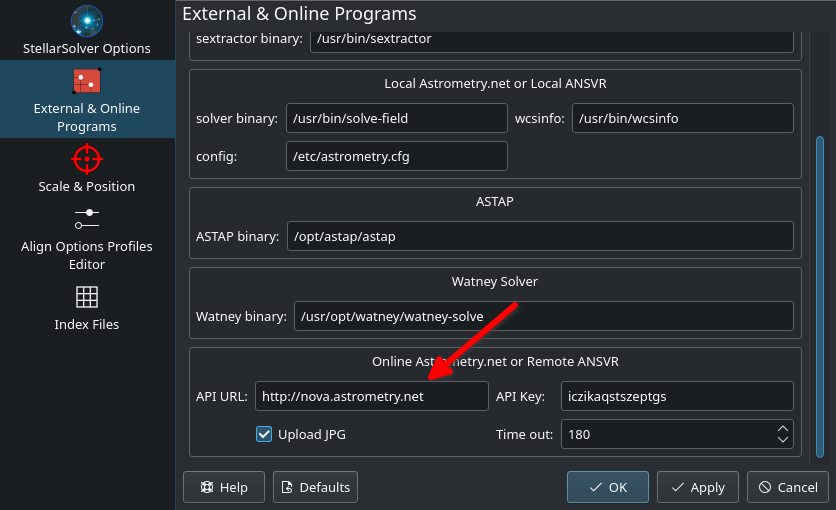
After installing the ANSVR server and downloading the appropriate index files for your setup, make sure ANSVR server is up and running and then go to Ekos Alignment options where you can simply change the API URL to use the ANSVR server as illustrated below:

astrometry windows ansvr

Do not forget to include the full URL including the HTTP part. In Ekos Align module, you must set the solver type to Online so that it uses the local ANSVR server for all astrometry queries. Then you can use the align module as you would normally do. 

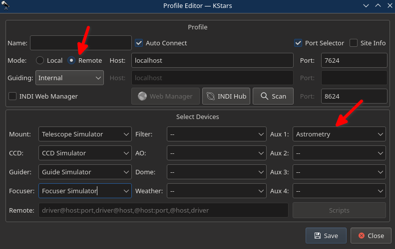
Remember as indicated above that StellarMate already includes astrometry.net. Therefore, if you would like to use StellarMate remotely to solve your images, simply change the solver type to Remote and ensure that your equipment profile includes Astrometry driver which can be selected under the Auxiliary dropdown. This is applicable to all operating systems and not just Windows.

Download Index Files

For offline (and remote) solvers, index files are necessary for the solver to work. The complete collection of index files is huge (over 30 GB), but you only need to download what is necessary for your equipment setup. Index files are sorted by the Field-Of-View (FOV) range they cover. There are two methods to fetch the necessary index files: The new download support in Align module, and the old manual way.

Automatic Download

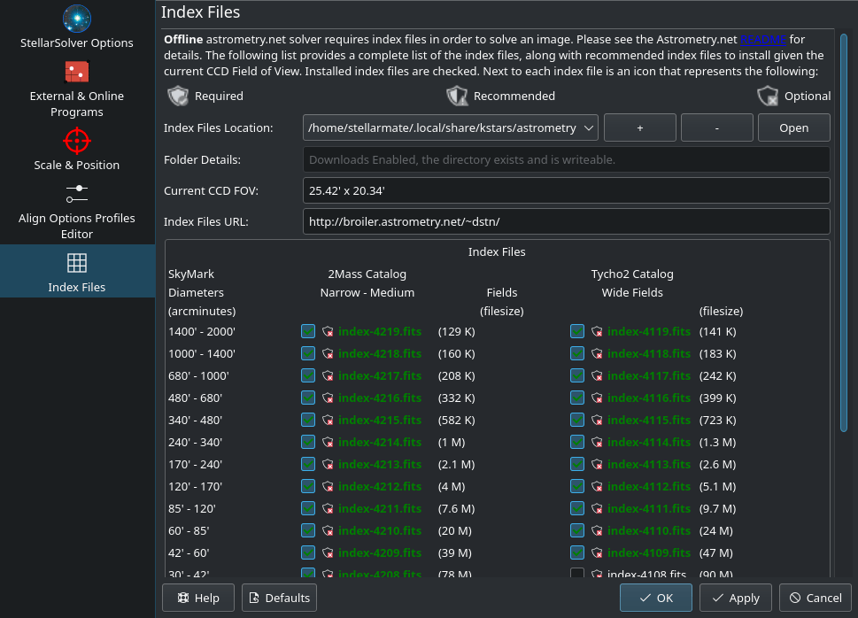
astrometry indexes settings

Automatic download is only available for Ekos users on Linux & macOS. For Windows users, please download ANSVR solver.

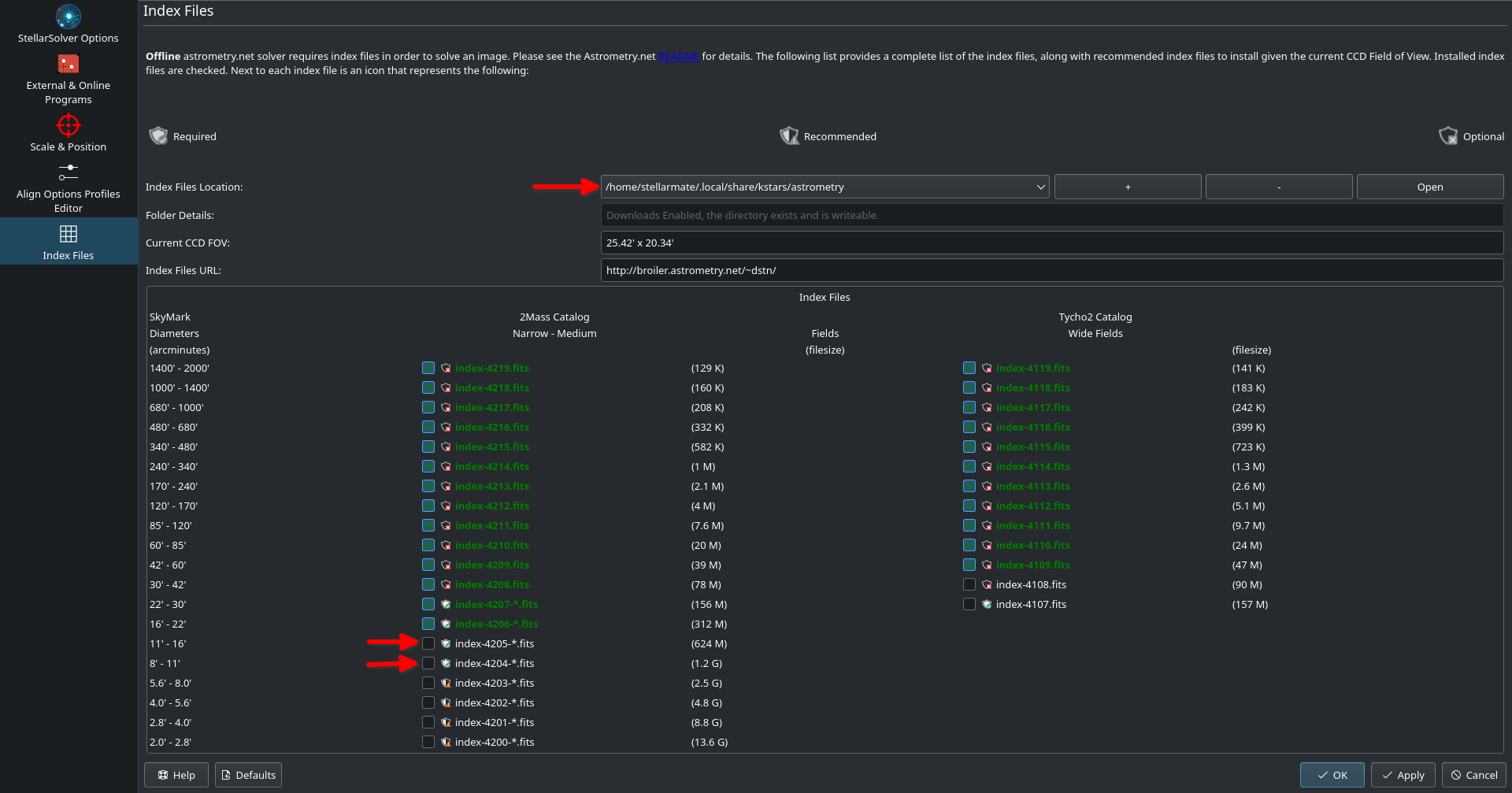
To access the download page, click the Options button in the Align module and then select Astrometry Index Files tab. The page displays the current FOV of your current setup and below it a list of available and installed index files. Three icons are used to designate the importance of index files given your current setup as following:

  • Required Required
  • Recommended Recommended
  • Optional Optional 

You must download all the required files, and if you have plenty of hard drive space left, you can also download the recommended indexes. If an index file is installed, the checkmark shall be checked, otherwise check it to download the relevant index file. By default, StellarMate comes pre-installed with index files 4206 to 4219. Due to size restrictions, indexes 4204 and 4205 are not included in the official StellarMate OS image. It is recommended to download them. From Astrometry Index Files tab, click on Index File Location combo and select the first entry below All Sources. Once selected, you should be able to download the necessary index files as illustrated below.

Astrometry Settings

Please only download one file at a time, especially for larger files. Once you installed all the required files, you can begin using the offline astrometry.net solver immediately.

Manual Download

You need to download and install the necessary index files suitable for your telescope+CCD field of view (FOV). You need to install index files covering 100% to 10% of your FOV. For example, if your FOV is 60 arcminutes, you need to install index files covering skymarks from 6 arcminutes (10%) to 60 arcminutes (100%). There are many online tools to calculate FOVs, such as the Astronomy tool.

Index FilenameFOV (arcminutes)Debian Package
index-4219.fits 1400 - 2000 astrometry-data-4208-4219
index-4218.fits 1000 - 1400
index-4217.fits 680 - 1000
index-4216.fits 480 - 680
index-4215.fits 340 - 480
index-4214.fits 240 - 340
index-4213.fits 170 - 240
index-4212.fits 120 - 170
index-4211.fits 85 - 120
index-4210.fits 60 - 85
index-4209.fits 42 - 60
index-4208.fits 30 - 42
index-4207-*.fits 22 - 30 astrometry-data-4207
index-4206-*.fits 16 - 22 astrometry-data-4206
index-4205-*.fits 11 - 16 astrometry-data-4205
index-4204-*.fits 8 - 11 astrometry-data-4204
index-4203-*.fits 5.6 - 8.0 astrometry-data-4203
index-4202-*.fits 4.0 - 5.6 astrometry-data-4202
index-4201-*.fits 2.8 - 4.0 astrometry-data-4201-1
astrometry-data-4201-2
astrometry-data-4201-3
astrometry-data-4201-4
index-4200-*.fits 2.0 - 2.8 astrometry-data-4200-1
astrometry-data-4200-2
astrometry-data-4200-3
astrometry-data-4200-4

The Debian packages are suitable for any Debian-based distribution (Ubuntu, Mint...etc). If you downloaded the Debian Packages above for your FOV range, you can install them from your favorite package manager, or via the following command:

sudo dpkg -i astrometry-data-*.deb

On the other hand, if you downloaded the FITS index files directly, copy them to /usr/share/astrometry directory.

It is recommended to use a download manager as such DownThemAll! for Firefox to download the Debian packages as browsers' built-in download manager may have problems with download large packages.

How to Use?

Ekos Align Module offers multiple functions to aid you in achieving accurate GOTOs. Start with your mount in home position with the telescope tube looking directly at the celestial pole. For users in Northern Hemisphere, point the telescope as close as possible to Polaris. Initial 2-3 star alignment might be required depending on your mount make:

  • EQMod, Celestron Aux (e.g. Evolution), AstroTrac: No need to perform initial alignment, Ekos alignment module can work with the mount right away after power up given the mount is in its home position.
  • All other Mount drivers: Must intially perform 2-3 star alignment using the handset before you can use the Ekos alignment module.

Ekos Alignment module features the following functions:

  • Optical Train: Select which optical train to use for alignment. Usally, it is the Primary optical train used in Camera module as well. Edit the optical train to ensure that the correct camera and telescope are selected. If using a focal reducer or balow, please specify it in the train configuration.
  • Capture & Solve: Capture an image and determine what region in the sky the telescope is exactly looking at. The astrometry results include the equatorial coordinates (RA & DEC) of the center of the captured image in addition to pixel scale and field rotation. Depending on the Solver Action settings, the results can be used to Sync the mount or Sync and then Slew to the target location. For example, suppose you slewed the mount to Vega then used Capture & Solve. If the actual telescope location is different from Vega, it will be first synced to the solved coordinate and then Ekos shall command the mount to slew to Vega. After slew is complete, the Alignment module will repeat Capture & Solve process again until the error between reported and actual position falls below the accuracy thresholds (30 arcseconds by default).
  • Load & Slew: Load a FITS or JPEG file, solve it, and then slew to it.
  • Polar Alignment Assistant: A simple tool to aid in polar alignment of German Equatorial Mounts.

Warning! Never solve an image at or near the celestial pole (unless Ekos Polar Alignment Assistant Tool is used). Slew at least 20 degrees away from the celetial pole before solving the first image. Solving very close to the poles will make your mount pointing worse so avoid it.

Plate Solve Capture Settingsastrometry settings

Configure plate solving capture settings:

  • Exposure: Exposure duration in seconds
  • Bining: Camera binning (2x2 is by default). Use 2x2 or 4x4 to speed up the process.
  • Gain: For cameras supporting gain, set the desired gain.
  • ISO: For cameras supporting ISO (e.g. DSLRs), set the desired ISO.
  • Dark: Perform dark subtraction if a suitable dark frame is found in the Dark Library.
  • Filter: If a filter wheel is used, then use this filter when capturing align images regardless of filter used in other modules.
  • Solver Mode: Select solver mode (StellarSolver or Remote). Remote solver is only available when connecting to a remote device.

By default, the solver will search all over the sky to determine the coordinates of the captured image. This can take a lot of time; therefore, in order to speed up the solver, you can restrict it to only search within a specified area in the sky designated by the RA, DEC, and Radius options above.

Astrometry.net Settings

Options for offline and online solvers.

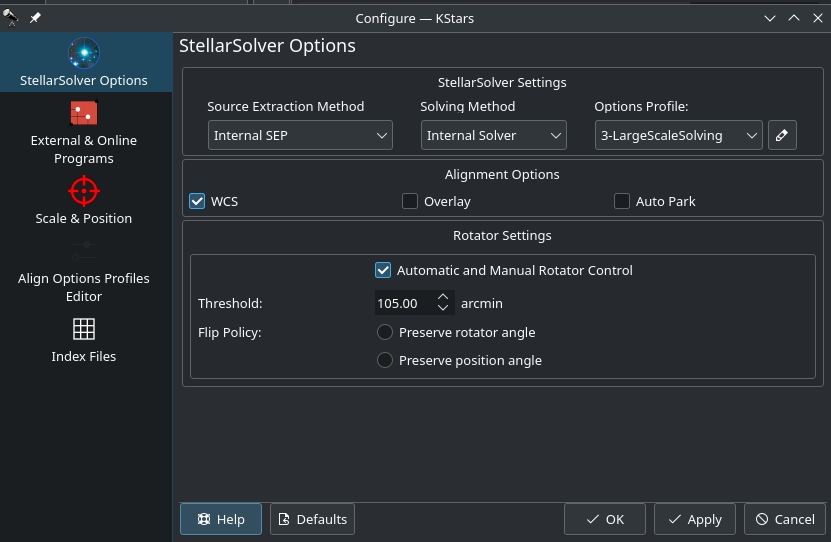
stellarsolver options

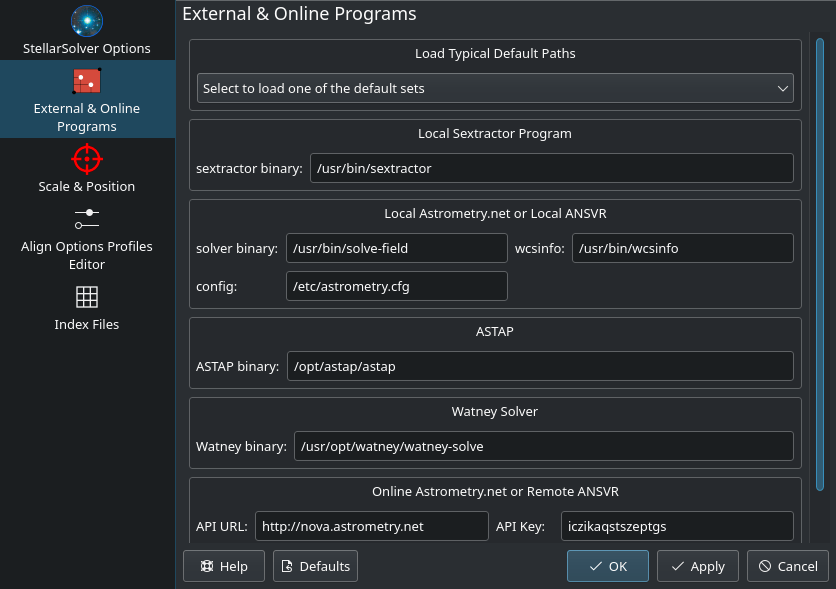
Most of the options are sufficient by default. If you have astrometry.net installed in a non-standard location, you can change the paths as necessary.

  • Rotator: Rotator threshold in arc-minutes when using Load & Slew. If the difference between measured position angle and FITS position angle is below this value, the Load & Slew operation is considered successful.
  • Time out: Timeout in seconds to wait for astrometry solver to complete.
  • WCS: World-Coordinate-System is a system for embedding equatorial coordinate information within the image. Therefore, when you view the image, you can hover it and view the coordinate for each pixel. You can also click anywhere in the image and command to the telescope to slew there. It is highly recommeneded to keep this option on.
  • Overlay: Overlay captured images unto the sky map of KStars.
  • Upload JPG: When using online astrometry.net, upload all images are JPEGs to save bandwidth as FITS images can be large.
  • Auto Park: Automatically park the mount after completing Polar Alignment Assistant Tools.

Warning: Turning Auto Park off might lead to inaccurate results.

Solver Options

Ekos selects and updates the optimal options by default to accelerate the performance of the solver. You may opt to change the options that are passed to the solver in case the default options are not sufficient.

Imaging Options

  • Use Scale: Set image scale to speed up solver as it does not have to search index files of different image scales.
    • Low: The lower end of the imager scale, calculated as a little smaller than the shorter dimension of the image.
    • High: The high end of the imager scale, calculated as a little bigger than the longer dimension of the image.imaging options
    • Units: The units of the imager scale bounds above.
      • dw: degree width
      • aw: arcminute width
      • app: arcsecs per pixel
    • : Update Image Scale Bounds from the currently active camera and telescope combination.
  • Auto Update: Automatically update image scale values when CCD and/or Mount parameters are updated.
  • Down Sample: Downsample the image to shrink its size and speed up the solver.
    • Auto: Automatically determine downsample value based on image size

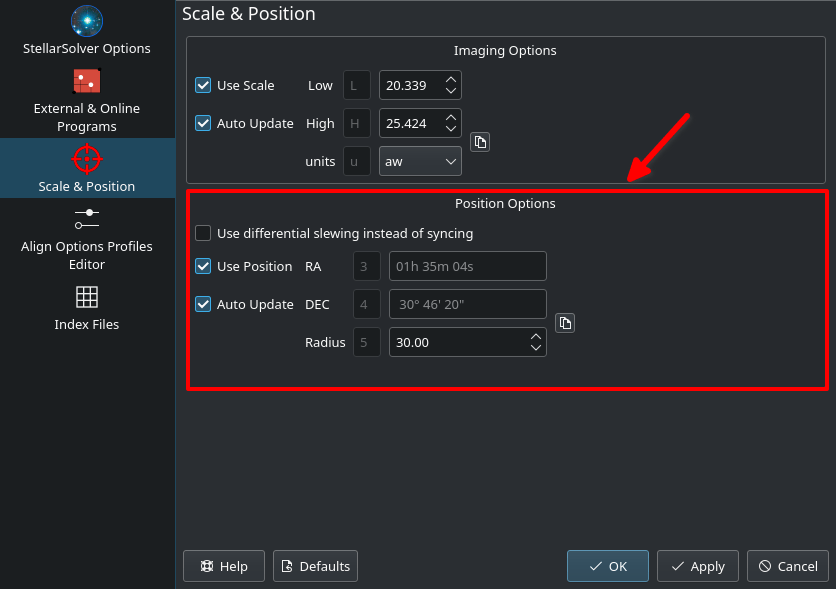
Position Options

  • Use differential slewing instead of syncing: Do not use Sync when Slew to Target is selected. Use differential slewing to correct for discrepancies. This is useful on some mounts (e.g. Paramount).
  • Use position: Set estimated position to speed up astrometry solver as it does not have to search in other areas of the sky.
    • RA: The RA of the Estimated Telescope/Image Field Position in hh:mm:ss notationposition options
    • DEC: The DEC of the Estimated Telescope/Image Field Position in dd:mm:ss notation
    • Radius: The Search Radius for the Estimated Telescope/Image Field Position in degrees.
    • : Update coordinates to the current telescope position.
  • Auto Update: Automatically update position coordinates when mount completes slewing.
  • Custom: Additional optional astrometry.net options.

If solving always fail even though the image contains lots of focused stars, then it is likely that either the frame field of view (FOV) and/or mount position is wrong. Turn off Use Scale or Use Position then try solving again. If the solving succeeds then that confirms that either the FOV scale or position are indeed incorrect.

Capture & Solve

Using Ekos Alignment Module, aligning your mount using the controller's 1, 2, or 3 star alignment is not strictly necessary, though for some mounts it is recommended to perform a rough 1 or 2 star alignment before using Ekos alignment module. If you are using EQMod, you can start using Ekos alignment module right away. A typical workflow for GOTO alignment involves the following steps:

  1. Set your mount to its home position (usually the NCP for equatorial mounts)
  2. Select Slew to Target in the Solver Action.
  3. Slew to a nearby bright star.
  4. After slew is complete, click Capture & Solve

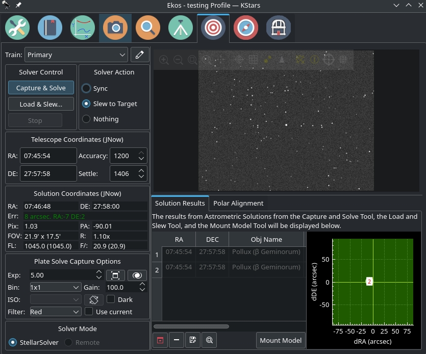
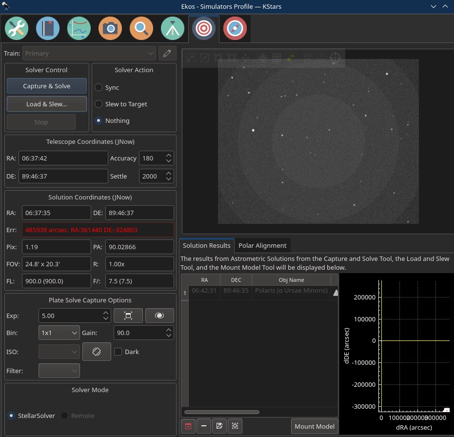
If the solver is successful, Ekos will sync and then slew to the star. The results are displayed in the Solution Results tab along with a bullseye diagram that shows the offset the reported telescope coordinates (i.e. where the telescope thinks it is looking at) vs. its actual position in the sky as determined by the solver.

Each time the solver is executed and returns successful results, Ekos can run on the following actions:

  • Sync: Syncs the telescope coordinates to the solution coordinates.
  • Slew to Target: Syncs the telescope coordinates to the solution coordinates and then slew to the target.
  • Nothing: Just solve the image and display the solution coordinates.

Troubleshooting

Sometimes, the solver would fail to solve an image for various reasons. Here are some tips to get you started in the right direction:

CauseActionEkosApp
Insufficient stars. Astrometry requires a few clearly visible and defined stars.
  1. Increase Exposure Time.
  2. Increase Gain and/or ISO settings.
  3. Change binning to 2x2 or 4x4
  4. Enable Dark frame subtraction. This helps in reducing the noise in the image.
Change Camera Settings in Ekos Alignment module.  Edit Align presets and change camera settings. 
Unfocused image. Focused star field is necessary for astrometry to work. Focus the camera until you get pin-point stars. Focus camera automatically or manually via Focus module. Focus camera automatically or manually via Focus module. 
Wrong Field of View value. Ekos displays the FOV in arcminutes.
  1. Verify your equipment FOV using online FOV calculator (Imaging Mode).
  2. Ensure the telescope focal length is correct.
  3. If using a reducer/corrector, then you must specify this value in the Optical Train.
  4. FOV depends on camera pixel size in micrometers. While it is very rare for this value to be incorrect, double check the camera pixel size is reported correctly in INDI Control Paneli> → Image Info tab.
   
Wrong Mount position. Astrometry works when the mount is relatively close to the GOTO target. If it is too far away (more than a couple of degrees) then astrometry may fail.
  1. For handset-controlled mounts, ensure a successful completion of 2-star or 3-star alignment routines before connecting the mount to StellarMate. It's recommended to turn off DST (Daylight Time Savings) as this might interfer with time handling in StellarMate.
  2. For direct-controlled mounts (EQMod, Celestron WiFi..etc), ensure that the mount is powered in its correct home position.
  3. Ensure that the date and time are correct. Incorrect time may lead the mount to a totally different location in the sky.
  4. Ensure geographic location is correct.
  5. While polar alignment is not strictly necessary for accurate GOTO (it mostly affects tracking accuracy). It's recomended to have equatorial mounts polar aligned.
  6. Do the RA/DE coordinates of the telescope make sense? By default, the solver searches within 30 degrees of the current mount location. If the mount is way off in the sky, the solver would fail. If this happens, go back to your parking home position and then slew to a nearby star. If the star is off by more than 30 degrees, then there is something wrong with the mount, time, and location settings so check each of those.
  SM App syncs the device time and location from the phone/tablet GPS automatically upon connection.
Missing astrometry index files By default StellarMate come preinstalled with index files 4206 to 4219, but if your FOV is on the narrower scale, you might need to install more index files.    
Automatic Downsampling
  • Automatic downsampling is turned on by default. It essentially reduces the size of your image before it is fed to the solver. For most users, this option improves solver efficiency. However, it can create issues for others. Go to Astrometry options and turn off automatic downsampling and if that doesn't work, try turning off downsampling completely.


Subcategories